
| Article number: | QHY5III178C |
| Availability: | More on the Way to us |
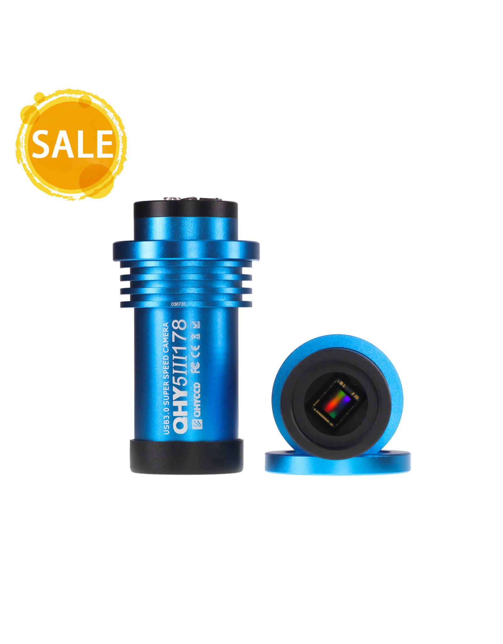
| Model | QHY5III178 |
| CMOS Sensor | Sony IMX178 |
| Color/Mono | Mono Only (ColorVersionDiscontinued in2022) |
| FSI/BSI | BSI |
| Pixel Size | 2.4um |
| Pixel Array | 3072*2048 |
| Effective Pixels | 6.3MP |
| Sensor Size | 1/1.8inch |
| Frame Rate @Full Frame | 50FPS |
| Frame rate @ROI readout | 100FPS@1528*1024190FPS@764*512 |
| Ful Well Capacity | 15ke- |
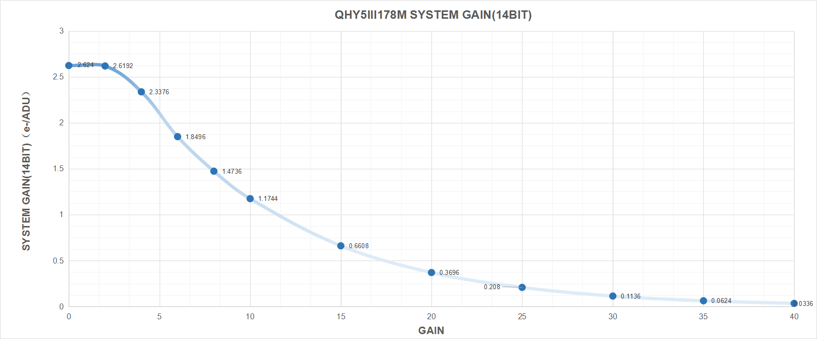
| A/D | 14bit |
| Computer Interface | USB3.0 |
| Non-volatile memory / On camera storage | Build-in total 512Kbytes Flash Memory. 100Kbytes user-accessible space |
| Guide Port | St4 |
| Telescope Interface | 1.25-inch, CS mount |
| Weight | 86g |
The camera requires an input voltage between 11V and 13.8V. If the input voltage is too low the camera will stop functioning or it may reboot when the TEC power percent is high, causing a drain on the power. Therefore, please make sure the input voltage arrived to the camera is adequate. 12V is the best but please note that a 12V cable that is very long or a cable with small conductor wire may exhibit enough resistance to cause a voltage drop between the power supply and the camera. The formular is: V(drop) = I * R (cable). It is advised that a very long 12V power cable not be used. It is better to place the 12V AC adapter closer to the camera.
First connect the 12V power supply, then connect the camera to your computer via the USB3.0 cable. Make sure the camera is plugged in before connecting the camera to the computer, otherwise the camera will not be recognized. When you connect the camera for the first time, the system discovers the new device and looks for drivers for it. You can skip the online search step by clicking “Skip obtaining the driver software from Windows Update” and the computer will automatically find the driver locally and install it. If we take the 5IIISeries driver as an example (shown below), after the driver software is successfully installed, you will see QHY5IIISeries_IO in the device manager.
Please note that the input voltage cannot be lower than 11.5v, otherwise the device will be unable to work normally.
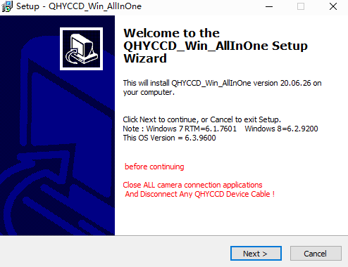
All-in-one Pack (Windows) is for all QHYCCD USB3.0 devices, including all Cooling CMOS cameras, QHY5III and QHY 5II series, QHYCFW3. We recommend you choose “Stable Version” as usual.
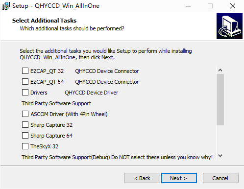
In this pack there are:
1. System driver. It must be installed to make devices work.
2. EZCAP_QT: it’s developed by QHYCCD which could be used in QHY devices tests, simple capture tasks, and above all, the management of updates. So even if you won’t use EZCAP_QT as your main capture software, we suggest you install it to get the latest information of QHY drivers/SDK updates.
3. Ascom driver: Ascom Platform is supported by most astronomy devices which connect to Windows.
4. SDK: SDK is the file of “.dll” format. With this the device can be identified in other capture software.
5. SkyX Plugin: special support for SkyX.
6. QHYCCD BroadCast WDM Driver: It is a broadcast driver that supports QHYCCD cameras with video broadcast function, which can meet the needs of customers to send video images to other target software.
How to install it?
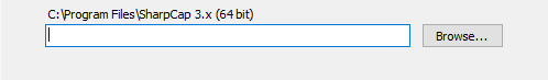
Take SharpCap (x64) for example:
Before the installation, make sure you’ve already installed SharpCap (X64) on your PC;
Then click ”Third Party Software Support” – “SharpCap 64”, the pack will detect the location of SharpCap files and install automatically; if not, please manually select root directory of SharpCap where you installed it, like: C:\Program Files\SharpCap 3.2 (64 bit)
Here we mainly take QHY5III462C as example. This User Guide can be applied to all QHY5III series Camera.
![]()
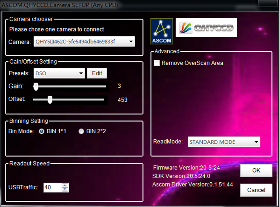
Adjust OFFSET. You will find that when the lens cover is closed and the image is completely black, the background of the image is still not completely black. Therefore, you need to adjust the OFFSET value to make the image darker. Generally speaking, for planetary shooting, setting the image background to very dark is not a big problem. For deep space shooting, a certain background should be retained, and it should not be completely black, otherwise it will lead to the loss of a weak background cloud.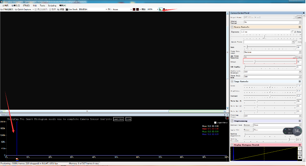
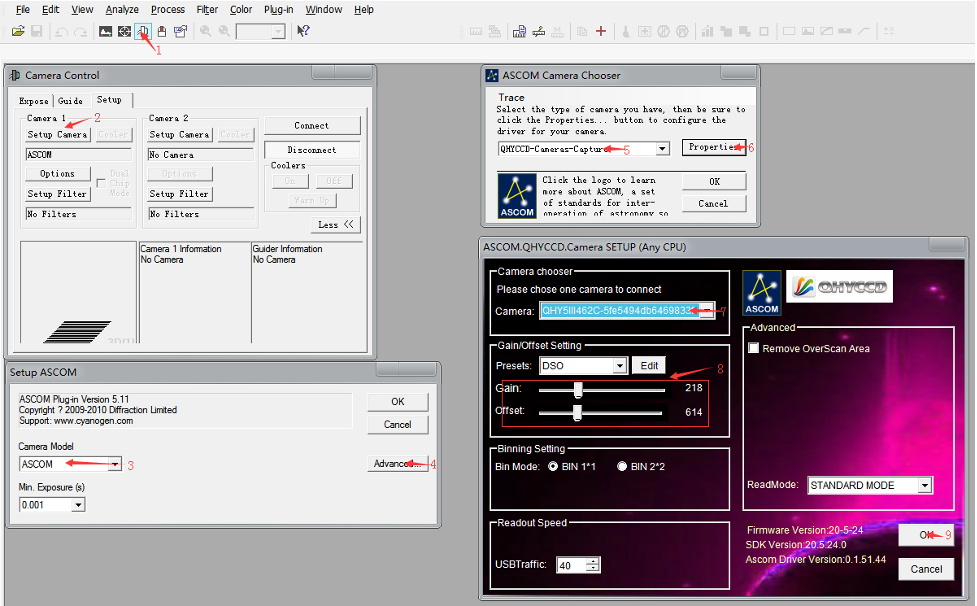
There are many astronomical software support ASCOM, you can connect QHY5III462C through ASCOM. Note that currently QHY5III462C only supports the ordinary ASCOM shooting mode, and does not yet support the ASCOM video mode. In order to obtain the maximum dynamic range and effect, the ASCOM driver uses the maximum number of digits transmission by default (for QHY5III462C, 12-bit), the image is stored in a 16-bit format, and the lower bits are filled with zeros.
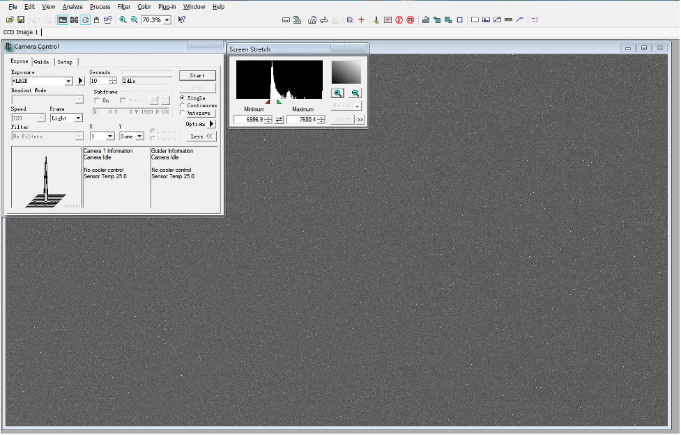
Use MAXIMDL for Plantery Imaging
When changing the exposure time to a long exposure time, the CMOS chip may output a few frames of short exposure. These frames may be output, but the subsequent frames will be normal long exposure frames.
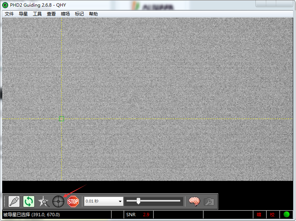
Using PHD for Guiding
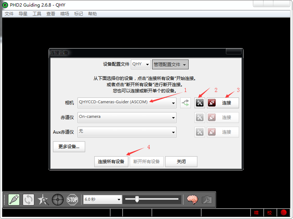
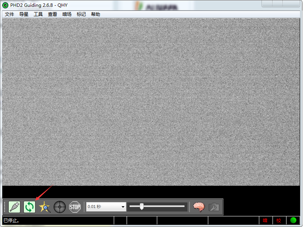
Select a star point on the screen, a green frame appears, and then select to start calibrating the equatorial mount and guide star.
QHYCCD BroadCast WDM Camera is a broadcast driver that supports QHYCCD cameras with video broadcast function, which can meet the needs of customers to send video images to other target software. For example, use sharpcap to connect a WDM-enabled camera, and the sharpcap display video image can be sent to other WDM-supported software for display, which is suitable for video online broadcast applications.
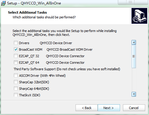
The installation process is over, right-click the computer to find the device manager, and check that the image device name is QHYCCD BroadCast WDM Camera, which means the installation is successful.
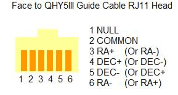
QHY5III Guiding Line Sequence Definition

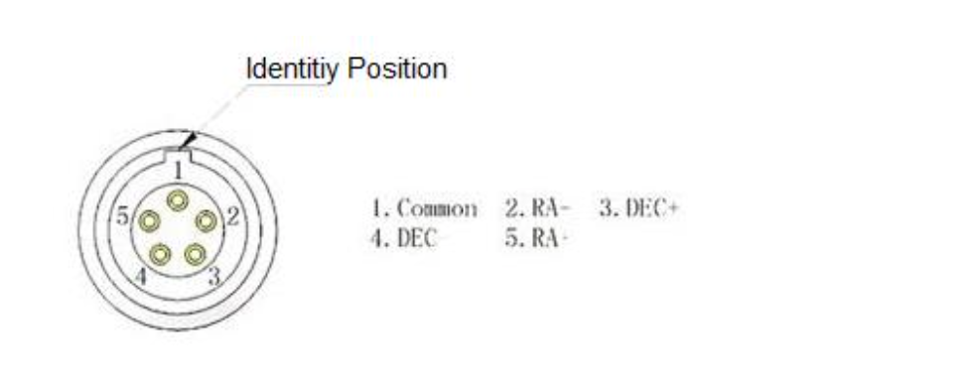
The guide circuit contains an optocoupler isolator. The COMMON pin is generally connected to GND. Usually the four direction pins from the equatorial mount are internally pulled up on the equatorial mount circuit, so when the QHY5III sends out the guide star pulse, the optocoupler pulls it down to realize the output of the guide star command.

The line sequence of the socket at the equatorial mount is

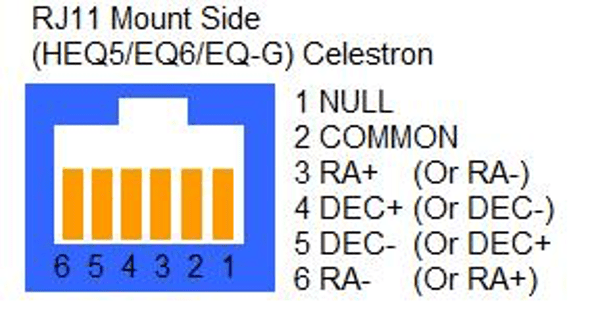
If you use other types of equatorial mounts, please confirm whether the wire sequence is the same as the above.
Because QHY5III series cameras have a very high frame rate and data volume, not all computers can reach the maximum frame rate. Generally I7 quad-core is no problem. However, the CPU occupancy rate will also affect the maximum frame rate, so when using QHY5III, try to close other programs that occupy the CPU and free up the CPU to process the data. If the CPU usage is too high, the program will respond slowly or even crash.