How to Collimate your Optics Using a Laser Collimator
- Posted on
- By Howie Glatter
Collimation of a telescope's optics is a critical bit of maintenance that should be checked as often as possible. To maximize the performance of your optical instrument you need to ensure that the optics are properly aligned at all times. Today, the easiest and quiclkest method of collimationis with a laser collimator. Here is an informative article from the late great wizard of collimation , Howie Glatter, who will explain the entire process for each different type of telescope.
HOWIE GLATTER’S LASER COLLIMATOR PAGE
Barlowed laser collimation is a technique developed by Nils Olof Carlin for adjusting the angular alignment of the Newtonian primary mirror. It projects a shadow of the mark on the center of the primary up to the face of the collimator. The primary is adjusted by centering the mark's shadow on the face of the collimator. The adjustment is insensitive to inacuracy or "slop" in the fit of the collimator in the focuser.
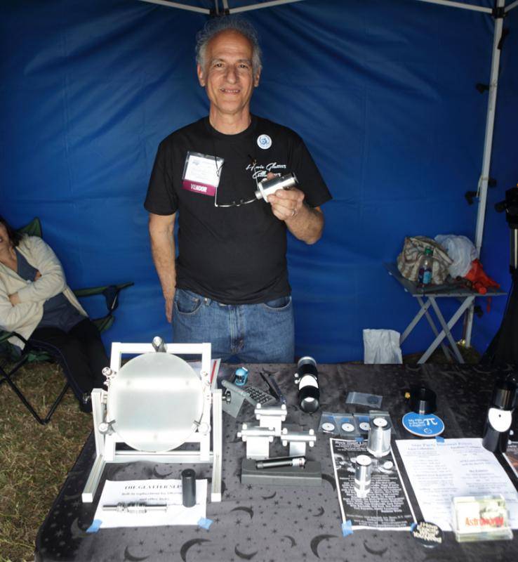
My Self-Barlowed collimator has a Barlow attachment that screws to the laser aperture for making the primary adjustment. The Barlow attachment is a disc with a small barlow lens mounted in it's center hole, and a flat white front surface as a screen. It makes the Barlow procedure more compact and convenient. The Barlow attachment fits the threaded aperture of any of my holographic collimators, and it can be purchased separately as an additional accessory by those who already have the holographic collimator.
NEW INFORMATION ABOUT BARLOWED LASER COLLIMATION AND MY BARLOW ATTACHMENT IS HERE, UNDER NEWTONIAN COLLIMATION
This website is concerned with the collimation of astronomical telescopes. In order to achieve the best possible resolution and contrast in images, the optical elements of a telescope must be put into near-perfect alignment. Laser collimation is a relatively new way of accurately and precisely adjusting the alignment of a telescope's optical elements.
Important definitions:
Collimation - the adjustment of the position and orientation of optical elements within a telescope (or other optical instrument) to achieve optimum performance.
Axis - an imaginary line passing through the center of an optical element and perpendicular to the plane of the element .
When performed with accurate tools and correct technique, the various methods of telescope collimation will converge to the same result, however, laser collimation has so many advantages that, in my opinion, it is the method of choice. When I first tried it on my Newtonian telescope, I found it so fast and accurate that I felt I was somehow cheating. Previously I had used a sight tube, which took awhile and had less accuracy and precision. At first I was ambivalent about use of the laser because I felt it was good for the novice to learn to adjust the mirrors by looking through the eyepiece holder, which teaches familiarity with the optical system. I felt the laser was like giving pocket calculators to kids who should be studying multiplication tables. I soon realized that collimating with the laser gave as much insight into optical alignment as conventional collimation. The fact that collimation could be done with ease in the dark also seemed like a great advantage. Because I was making them myself, I felt I could produce a very high quality collimator at a reasonable price, and put more of them into people's hands (I love machining stuff anyway). It seems to be working out well, and I feel lucky that I can earn a living from making and selling something I believe in.
The lasers in my collimators are class IIIa lasers (maximum beam power: 5 thousandths of a Watt), and are quite safe if used with reasonable precaution. Direct or mirror-reflected eye exposure to the laser beam should always be avoided! You must be careful when collimating to ensure that the beam does not enter anyone's eye. There is no problem in viewing the beam's impact directly on a surface as long as the surface produces a diffuse reflection. The beam impact may also be safely viewed on a mirror or lens surface if the reflected or transmitted beam is not directed towards your eye. Information from studies I have seen suggests that in order to induce permanent damage, a class IIIa laser beam must stay focused on the retina for a long time. It's unlikely for this to happen because the pupil is a very small target and because we have a blink and aversion reflex to bright light. However, all precautions should still be followed to avoid the beam entering anyone's eye! A badly miscollimated Newtonian or Cassegrain telescope may allow the beam to exit the front of the telescope, so when collimating, check first by pointing the telescope at a wall or screen to see if the beam is getting out. With unobstructed telescopes such as refractors, the beam will always exit the front of the telescope, so run a strip of masking tape across a diameter of the dew cap opening as a safety beam stop.
Inside the collimator is a solid-state laser diode, which emits an intense laser beam through a front aperture, exactly along the central axis of the cylindrical collimator body. The beam acts as a "reference line" from which alignments are made. For a laser collimator it is of supreme importance that the beam be aligned with the collimator's cylindrical axis, for if it is not, the resultant "alignment" of the telescope optics will be off-center and asymmetric, and the telescope will produce aberrated images.
When I started manufacturing laser collimators I realized that in order to produce consistent and accurate results they must be highly resistant to mechanical shock, so that internal laser alignment is maintained. I experimented with this aspect of collimator construction and developed a design which tremendously increased shock resistance. After aligning the laser within 15 arc seconds, I shock test each collimator by whacking it against a block of urethane plastic (urethane prevents marring), striking it at least a dozen times on three axis. I then recheck the laser alignment, and if it has not changed the collimator passes. I believe this is the most important difference setting my collimator apart from all others I know of. They will withstand a shock equivalent to dropping from eyepiece position, up the ladder on a big Dob, without alteration of laser alignment.
The holographic collimator has a removable diffractive optical element ("hologram") placed in the beam, just ahead of the laser. It diffracts light from the laser to project a diverging, symmetrical pattern around the central beam which is quite useful for centering optical elements. My standard pattern is an illuminated ten line by ten line grid, forming a large square box enclosing eighty-one smaller squares. It covers a wider angle (21 degrees) than any other holographic collimator, which allows direct centering of f/ 2.7 to f/ 35 optics. It may seem counter-intuitive, but the square grid pattern gives greater sensitivity for centering circular optics of arbitrary size. If a mirror or lens is decentered by only a small amount against the grid pattern, it produces a proportionately larger asymmetry in the intersection points of the grid lines with the perimeter of the optic. Cross-hair patterns do not have this property.
The diffractors are individually fit to their collimators for maximum alignment accuracy, so if you have one of my holographic collimators and know someone else who has one, be careful not to switch diffractors. If switched, 15 second alignment accuracy in the holographic mode is likely to be lost, however, they will still fall within the several arc minute alignment tolerance of most other laser collimators.
Because there are some collimating situations in which the diffracted pattern is unnecessary or unwanted, or maximum power in the central beam may be desired, the diffractor unscrews from the laser aperture, converting the holographic collimator to single beam mode. When it is screwed back it retains its alignment accuracy.
The beam from all red diode lasers used in collimators is fuzzy-edged and elliptical in cross-section. When collimating, you sometimes must judge the location of the center of the spot by eye. To improve collimating precision, all of my collimators (except 532nm) are supplied with a removable accessory plastic aperture stop having a 1mm hole, which push-fits into the laser aperture. It produces a tiny, circular beam impact which allows more accurate alignment. With the holographic collimators, it is not used at the same time as the holographic feature, and the diffractor must be removed to install the stop. With the stop inserted the beam impact at a distance of one meter or more looks like a star diffraction pattern, with a central dot surrounded by diffraction rings. The surrounding rings can help in centering the beam very accurately.
I offer the red holographic collimators with a choice of either 650 nanometer or 635nm wavelength. The two lasers have the same radiometric power output, but because the human eye's sensitivity to the shorter wavelength is greater, the 635nm. laser appears about two or three times brighter. The higher cost of 635nm laser diodes increases the collimator price $25, but it enables holographic collimation in brighter ambient light. If you intend to collimate in early twilight, it is a good choice. In darkness, however, the 650nm laser is quite adequate. Because single beam collimators concentrate all the laser light in the central beam, the 650nm laser is quite adequate for them.
I make a 532nm green holographic collimator which is bright enough to do holographic collimation in full daylight. Because the green laser module is larger than the red ones, I make the 532nm collimator in the 2"-1 1/4" combination size only. While the 532nm collimators are moderately shock resistant, they are not nearly as shock resistant as the red ones, and greater care should be taken to avoid dropping them.
I also sell green laser pointers for pointing out celestial objects and as finders mounted on the telescope tube. Regarding this, please see my website, www.skypointer.net. I have been asked if the green laser collimator can be used as a sky pointer. With the holographic diffractor removed, the answer is yes. However, it is pretty heavy; a little over a pound, and the battery cap/switch is not as convenient for pointing as the push button switch on the SkyPointer. Because of this, I do not recommend the collimator as a pointer.
I produce the collimators in three different body types : a 1 1/4" only , a 2"only , and a combination 2"-1 1/4" size. The Combination size is 2" at the rear and steps down to 1 1/4"at the front. The 2"- 1 1/4" or 2" collimator insures accurate alignment in a 2" eyepiece holder, but the 1 1/4" collimator is fine in a 2" holder if used with an accurate adapter bushing. The adapter can be itself checked for accuracy with the collimator by rotating the adapter and reclamping it; the laser spot should not wander.
Let me note here that watching a laser beam impact while rotating a collimator in an eyepiece holder is not a good test of a collimator's alignment. Due to clearance between the collimator and holder, the collimator may precess like a top, and even a good collimator's spot may travel in a circle. For a valid test of a collimator or adapter :
1. lock drawtube
2. note pecise spot location.
3. unclamp, rotate and re-clamp collimator or adapter.
4. check spot for wander.
In use, the laser collimator is placed in the telescope's eyepiece holder, and collimation begins by checking that the holder is correctly and stably aligned in relation to the telescope tube. Since laser collimation proceeds from the eyepiece axis, true alignment of, and with that axis is very important. In fact, eyepiece axis alignment problems are the greatest cause of laser collimation difficulty. Many people are shocked to see how much side motion or "wiggle" their eyepiece holder, drawtube or focuser displays. In many cases the laser beam impact on the objective lens or mirror may travel in a circle as a helical focuser is rotated, or jump back and forth as focus direction of a rack-and-pinion focuser is reversed. Another type of eyepiece holder instability, shown by motion of the beam impact, is tipping of the eyepiece or collimator as the eyepiece clamping screw is tightened. The collimator, with its light beam as a long "lever arm" is a very sensitive tool for detecting these kinds of problems. The problem should be fixed, or at least examined and understood before proceeding with laser collimation. If the eyepiece holder does not provide a stable pointing direction for the collimator, consistent results cannot be expected. However, even if the problems are not fixed, laser collimation of the telescope can be accomplished if the eyepiece holder is adjusted to a stable position and not disturbed over the course of collimation.
NEWTONIAN COLLIMATION
There are eight different alignments which should be checked and adjusted to completely align a Newtonian system, however, once initial alignment has been accomplished, most of these alignments are stable, and only two: the angular alignments of the primary and secondary mirrors, need to be periodically checked and corrected as necessary
For optimum performance, a Newtonian telescope's eyepiece axis must intersect the main tube optical axis, and in almost all Newtonians, the two axes should intersect at right angles. The alignment can be done using simple procedures that utilize the single beam collimator. You may also need a carpenter's or framer's square. One leg of the square should be as long as the tube's diameter. The secondary mirror and its holder should be temporarily removed, but the spider can be left in.
First, use the square to check that the front opening of the main tube is square with the tube, then measure back from the tube front edge to the laser beam, projected by the collimator from the focuser. Adjust the focuser by tipping it towards the front and back of the scope so that the tube front edge to laser beam distance is the same on the focuser side of the tube and on the side opposite the focuser. Some focusers have adjustment screws in their base for this, but if not, you can use shims or washers. This adjustment sets the tube and focuser axes square with each other.
Next, cut a stick or a strip of stiff cardboard to span the tube's inside diameter and mark its center. Place it in the tube, spanning the diameter at right angles to the focuser axis, and adjust the focuser by tipping it side to side so that the laser beam hits the mark. You can also check the beam centering within the tube with a tape measure or ruler. This adjusts the focuser axis to intersect the tube axis.
The secondary should now be replaced. In f/6 or slower telescopes the secondary mirror should be centered within the tube's diameter. In faster Newtonians the secondary should be slightly decentered away from the focuser. This is necessary if the secondary has been made the minimum size that will just intercept all of the converging light rays from the primary. In that case, the ellipse formed by the intersection of the plane of the secondary with the converging light cone from the primary has its center offset from the optical axis. If you know the amount of offset for your telescope, you may adjust the secondary mirror cell or spider to move the secondary away from the focuser by the required amount. This should be checked with a ruler or caliper, measuring from the secondary edge to tube wall.
Next, move the secondary parallel to the tube axis so that it is aligned with the focuser axis. When it is correctly aligned, the center of the secondary is actually offset or displaced towards the primary so that its edges will be centered in the light cone converging to the focal plane. You can look through the empty eyepiece holder and adjust the secondary so that its edges appear concentric with the top and bottom edges of the focuser tube. With a holographic collimator, you can adjust the secondary to center the projected pattern on it. Both methods produce the proper offset towards the primary. Some sources recommend placing a dot on the center of the secondary to position it, but the secondary should not be marked because unlike the primary, its center is in use. Also, this will not produce the proper offset towards the primary unless the dot is displaced towards the front edge of the secondary by a distance that will vary according to the particular telescope.
Next, rotate the secondary on the main tube axis so that the mirror faces the focuser squarely. Conventionally, this is done by looking through the open focuser and rotating the secondary so that its edge appears as circular as possible. This adjustment can be done with greater precision using a single beam collimator. Temporarily misadjust the secondary by tipping it either directly towards or directly away from the focuser using its angular adjustment screws. Then, rotate the secondary holder on the tube axis; the reflected laser spot will trace an arc on the primary at the bottom of the tube. Look at this spot from the front of the telescope with your eye gazing through a line between the secondary and the focuser. Rotate the secondary so that the laser spot reaches a point in line with both the secondary and focuser. Lock the secondary rotation adjustment at this point.
Check that the primary mirror is centered within the tube, so that the optical axis will coincide with the tube axis. Check it all around with a ruler, and adjust the cell centering if necessary.
Next, the angular alignment of the secondary mirror is adjusted so that the beam strikes the center of the primary mirror. With a single beam laser collimator and an unmarked primary it is impossible to judge this accurately by eye, so you will need a dot or "donut" placed on the center of your primary as an aid to precise beam centering. A donut is preferable, as a completely opaque dot will not allow reflection of the beam, preventing primary mirror alignment; however, a dot made with a permanent marker will transmit enough light to allow collimation. Don't worry about putting a dot on the primary: the center is not in use because it's in the shadow of the secondary. I supply self-adhesive collimation "donuts" with the collimators, and instructions for their safe placement.
Even if a primary mirror has no center mark, the secondary can still be adjusted if a holographic collimator is used. The secondary is then adjusted by centering the grid pattern on the edges of the mirror.
Next, the angular alignment of the primary is adjusted so that the beam folds back on itself, retraces its path, and returns to the laser opening in the front of the collimator. The returned beam can be seen striking the face of the collimator, and the primary is adjusted to move the beam impact towards the center of the collimator face until it disappears in the brightness of the laser aperture. With a solid tube, the best way to view the beam impact on the collimator face is from the front of the telescope, looking down the tube, by double reflection in the primary and secondary. You may need someone to help you by turning the primary adjustment screws while you look down the tube. With an open truss tube, the collimator face may be seen by reflection in the secondary. The primary adjustment can also be done by making the up and down going laser beam impact points on the secondary coincide.
BARLOWED LASER PRIMARY ADJUSTMENT
Normally, a telescope takes parallel light rays from a distant star and converges them to a point at the eyepiece focus. Barlowed laser collimation takes advantage of the fact that a telescope will work in reverse. Placing a colllimator into a barlow lens will cause the parallel rays of laser light to diverge, apparently from a point just behind the Barlow lens. The diverging rays projected from the laser-Barlow combination in the focuser are turned into a beam of all-parallel rays when they are reflected from the primary, except for where the center mark on the primary prevents the mirror from reflecting. This reflected beam, containing a superimposed shadow of the collimation target, is projected up to the secondary, and then reflected to the focusser.
If you placed your laser collimator into a conventional barlow lens, you need to attach a paper circle to the end of the barlow as a screen to view the shadow on. The paper circle needs to have a hole in it's center to pass the outgoing beam.
The primary tilt is now adjusted to center the target shadow around the hole. The position of the shadow on the screen is effected very little by motion of the illuminating beam. It is almost startling to see the shadow remain stationary as you "bend" the collimator and Barlow around in the focusser, and the fuzzy perimeter of the diverged laser beam moves all over the place.
My Self-Barlowed collimator has a Barlow attachment that screws to the laser aperture for making the primary adjustment. The Barlow attachment is a disc with a small barlow lens mounted in it's center hole, and a flat white front surface as a screen. It makes the Barlow procedure more compact and convenient. The Barlow attachment fits the threaded aperture of any of my holographic collimators, and it can be purchased separately as an additional accessory by those who already have the holographic collimator.
There is another method of primary adjustment using the Holographic collimator that also takes advantage of the telescope working in reverse to project the hologram pattern in a parallel beam. The pattern can be projected from the telescope, and the primary can be adjusted by observing the pattern projected on a screen or wall, and centering the pattern around the shadow of the secondary. If the secondary is offset, it also should be offset the same amount in the projection. This procedure facilitates solo primary mirror collimation, but I don't think it is as accurate as the previously mentioned methods.
REFRACTOR COLLIMATION
To reiterate the eye safety warning, the laser beam will always exit the front of a refractor, so run a wide strip of masking tape across the diameter of the dewcap opening to act as a safety beam stop. To collimate a refractor telescope the drawtube must first be aligned so that the laser beam passes through the center of the objective lens. The collimator is placed in the draw tube without using a diagonal prism or mirror, and the drawtube axis is checked for alignment by seeing if the beam passes through the center of the objective. With a single beam collimator you can cut a paper circle the same size as the front cell opening, and punch a small hole in its center. Place the paper circle in the lens cell and see if the laser beam passes through the hole.
Centering is also easily checked by holding a ruler across the front cell opening, with the beam grazing the ruler's edge. Check centering both horizontally and vertically.
With a holographic collimator the centering of the beam can be checked directly by symmetry of the pattern at the edges of the objective. If the drawtube alignment is off, it must be corrected before proceeding with collimation. Very few refractors have adjustments for this, so usually drawtube misalignment must be fixed by telescope mechanic work on the drawtube, focuser, or tailpiece. Shimming, filing, or machining may be required.
The next step is to adjust the angular alignment of the objective so that the beam, which is reflected from the exact center of the rear surface of the objective, is returned to the collimator face and centered on the laser aperture. The holographic collimator should be put in single beam mode for this, so that the diffracted pattern does not annoyingly interfere with viewing the reflected beam impact on the collimator face, viewed off-axis through the objective. This will also make the central beam brighter which will be helpful. Enough light is reflected even from an anti-reflection coated lens surface to perform this adjustment.
Some light will be reflected from each lens surface within the objective, although the reflection from the rear surface may be brightest. If the elements of the objective are accurately centered and collimated with respect to each other and have no wedge, all the reflections will coincide, forming one reflected spot. If there are multiple reflected spots, it is an indication of alignment problems within the objective. The collimator could then be used to diagnose and correct the inter-element misalignment.
CASSEGRAIN COLLIMATION
In a Cassegrain telescope all the optical elements should be perfectly centered on a common axis, and all should be perfectly square with that axis. This axis should also coincide with the axis of the telescope's tube.
The general procedure is to check that the back eyepiece holder or drawtube axis coincides with the main tube axis, and then put the secondary, primary, and corrector plate (if present) successively into alignment with that axis. The single beam collimator will allow eyepiece axis and secondary mirror alignment, but the holographic collimator is necessary for primary and corrector alignment.
First, the centering of the eyepiece or drawtube fitting at the back of the telescope should be checked by slightly withdrawing the collimator and measuring all around with a ruler or caliper between the collimator body outside diameter and the telescope tube outside diameter. Next, the secondary should be similarly checked for centrality within the tube with a ruler or caliper. Then the back can be checked for squareness by seeing if the laser beam strikes the center of the secondary. The alignment of the back axis can also be checked by measuring the beam centering within the tube with a cardboard strip marked at its center, placed within the tube as was done in Newtonian focuser alignment. If you are using a single beam collimator with a Cassegrain that has a corrector plate, beam centering on the secondary must be judged by eye (viewed by reflection in the primary). This is not the best practice, but by moving your gaze in a circle around the secondary while checking centering, accuracy can be improved. With the holographic collimator you can see if the target pattern is centered on the secondary.
At this point, I should mention that the laser beam impact on lens and mirror surfaces is seen only by light scattered from tiny particles of dust and dirt, and optical roughness. In very clean, sealed systems, such as Schmidt and Maksutov Cassegrains, it may be difficult to see these impacts. In such cases, visibility can be improved by lowering the ambient lighting, and opting for the 635nm, or 532nm collimator.
The next step is angular adjustment of the secondary so that the beam reflected from the center of the secondary is centered upon the laser aperture on the face of the collimator. This sets the secondary square with the optical axis.
The secondary will now reflect and project the holographic pattern upon the primary, and the primary should be centered within the pattern. The pattern is now reflected by the primary and projected in a collimated beam out the front of the telescope. The angular alignment of the primary is adjusted by projecting the pattern onto a surface or screen in front of the telescope and adjusting the primary to center the pattern around the shadow of the secondary. In the case of a corrector plate, if the pattern projected from the scope is undistorted, the corrector alignment is fine. If not, adjust the corrector to remove pattern distortion.
SCHMIDT-CASSEGRAIN COLLIMATION
The biggest problem in collimating Meade and Celestron SCTs is that the corrector plate, primary mirror, and back axis are not adjustable, and even the secondary has no centering adjustment. Only the secondary mirror angular alignment is user-adjustable.
Additionally, in some of these telescopes there is excessive clearance between the bearing surface on the outside of the baffle tube and the sliding bushing that the primary is mounted on. This allows the angular alignment of the primary to shift when the direction of focus adjustment is changed, and when the scope tube crosses the meridian when tracking the sky. The newest versions of Meade SCTs incorporate a primary mirror lock, intended to eliminate primary shift. If you don't have this feature, you should always finish your focusing adjustments and perform collimation by rotating the focus screw counterclockwise so that the mirror will be pushed upwards to the same angular orientation and cannot settle backward against the focus screw and nut's backlash. In addition, you should collimate with the scope oriented to the same side of the meridian each time. These precautions will minimize errors in collimation adjustment.
If all the non-user-adjustable alignments were correctly and permanently set at the factory, and there was no primary mirror shift, it would be a simple matter to collimate an SCT by adjusting the secondary so that the beam from a laser collimator mounted in the back folds on itself and retraces its path back into the laser aperture. This would set the secondary exactly square with the optical axis. However, because of possible misalignments in the non-adjustable elements, the best setting of the secondary may actually be tipped with respect to the optical axis. This is because tipping the secondary can partially (but never perfectly) compensate out some of the image aberration induced by the other misalignments.
Therefore, the best way to use laser collimators with SCTs is not to perform the initial collimation with them, but to use the collimator to measure and record the optimum secondary adjustment just after it has been found by using the star test. Once recorded, the optimum adjustment can be reproduced with the laser collimator alone whenever required. The star test adjustment, done under good seeing conditions, using the in-focus star image, is the most accurate and sensitive method of collimation. It need be done only once. The secondary is adjusted to produce the most compact image of a star at high power in the center of the field. The star test (and subsequent re-collimation with the laser collimator) should be done without using a diagonal, unless the diagonal is known to be accurately collimated itself. As soon as the secondary adjustment is judged to be as good as is possible, the eyepiece is removed and the single beam collimator (or holographic collimator in single beam mode) inserted in the back. It's important that the collimator be mounted accurately on axis so that the beam will strike the center of the secondary. Many back adapters can not be counted on to do this, and they should be checked by rotation at the threads while observing the laser impact on the secondary. The laser beam reflects from the secondary and returns back to impact the face of the collimator. The exact location of the beam impact is a measurement of the secondary setting. The beam impact can be seen from the front of the telescope, looking through the corrector plate, by double reflection in the primary and secondary. Some find it difficult to see the collimator face because of the restricted view. I make a side cut-out adapter tube that screws to the back of the telescope which makes it easy to see the collimator face directly.
Take careful note of the beam impact position so that you can re-collimate the secondary any time that it becomes necessary. You can place a mark on the face of the collimator at the exact location, but then the collimator must be inserted in the telescope back in the exact same rotational orientation each time. Any of my collimators can be used, but the 2" body collimator facilitates this with an index mark on its back edge that registers with an engraved reference grid on the front face.
SOME ADDITIONAL USES
Star diagonals can be aligned and centered by first collimating a scope without the diagonal, then inserting the diagonal in the optical path and adjusting the mirror or prism so that the telescope's alignment is restored.
Another application is checking the collimation of binocular viewers. The two eyepiece tubes should show the same telescope collimation when the collimator is successively inserted in them. The collimation can also be checked with the binocular attachment alone, by setting the attachment rigidly on a table or stand, and viewing the beam impacts on a screen at some distance (any built-in Barlow must be removed for this). The beam impacts should coincide.
The collimators are powered by a single 123A lithium cell (commonly used in point-and-shoot cameras), which maintains a stable output voltage for the 40 hour battery lifetime, giving maximum laser output. The collimators are supplied with one battery, plastic storage case, collimation "donuts", and instructions